23 Results
View results:
Sort by:
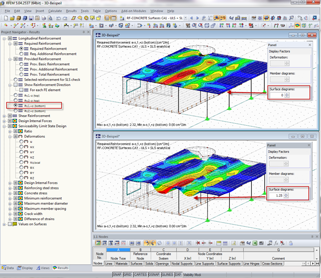
When calculating the surface reinforcement in RF-CONCRETE Surfaces, the result values for both surface sides +/- z are available. A previous post describes how to display the local surface sides in RFEM.
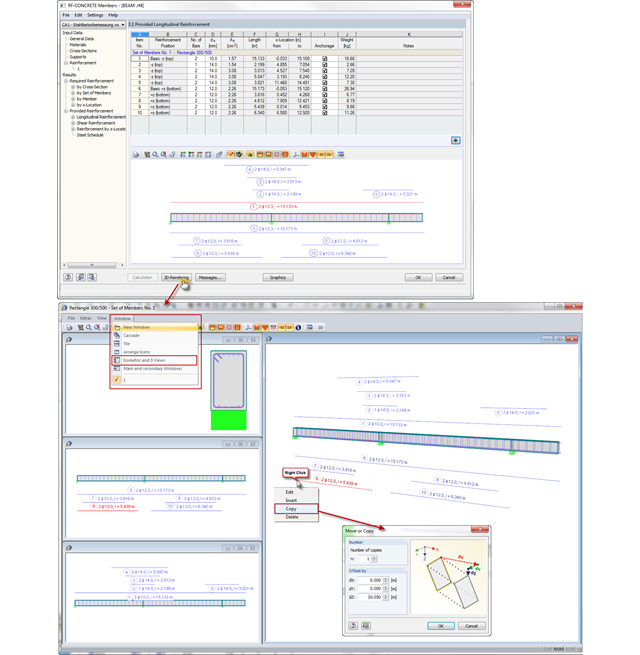
In CONCRETE and RF‑CONCRETE Members, you can open a dialog box with a 3D rendering of the existing reinforcement in Window 3.1 or 3.2. Now, you can also display different reinforcement views in several dialog boxes at the same time. The "Isometric and 3 Views" option known from RFEM is available here as well.
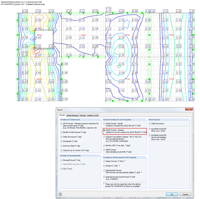
RF‑CONCRETE Surfaces performs the ultimate and the serviceability limit state design of slabs, plates, folded plates, and shells. In RFEM 5, the reinforcement resulting from this design can be displayed graphically on the surfaces of the structure using isolines. For the reinforcement design, it may be useful to export the results as isoline distribution in a DXF file in order to open them in a CAD application as background layers.
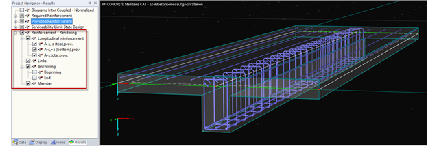
You can display the existing reinforcement of RF-CONCRETE Members not only in the module, but also in the RFEM graphical window and thus show the reinforcement for all members of the relevant RF-CONCRETE case.
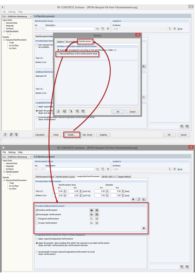
As of program version RFEM 5.06, you can not only perform the automatic arrangement of an additional reinforcement, but also define the surface reinforcement manually. In addition to the uniformly distributed basic reinforcement, you can define various surface reinforcements (per surface; rectangular, circular, or polygonal).
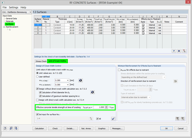
As of RFEM Version 5.06, there is the option in RF‑CONCRETE Surfaces to adjust the effective concrete tensile strength at the time of cracking. At the start of the SLS design, the program checks whether the internal forces can cause cracks in the concrete. For this, the effective concrete tensile strength at the time of cracking is applied. You can adjust the strength via the factor. The calculation details display the adjusted value.
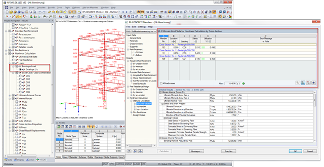
With RFEM 5.6.1103 and RSTAB 8.6.1103, there is an improved result output for the nonlinear calculation of reinforced concrete design in RF‑CONCRETE Members and CONCRETE. The new result windows include tables with a wide range of loading results; for example, governing load with the maximum ratio. In addition, you can now display the envelope results for the maximum ratio graphically.
![Parameters of Effective Slab Width (Figure 5.3 [1])](/en/webimage/009561/2419376/01-en-png.png?mw=640&hash=c76563b459152b19c98197ea6ba342be89d9a5bc)
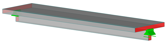
In the case of combined FEM structures (surface and member elements) as well as folded plate structures, it is possible to attribute a beam structure for the design on a member to a fictitious T-beam cross-section, whose geometry depends on the effective width. When using the "Rib" member type in RFEM, the stiffness is represented by a slab component (surface element) and a web component (member element). This approach has some design specifics that are explained in this article.
RFEM and the RF-CONCRETE add-on modules provide various options for the deformation analysis of a T-beam in the cracked state (state II). This technical article describes the calculation methods (C) and modeling options (M). Both the calculation methods and the modeling options are not limited to T-beams, but will only be explained using this system as an example.

This article describes how a flat slab is generated as a 2D model in RFEM and the loading is applied according to Eurocode 1. The load cases are combined according to Eurocode 0 and calculated linearly. In the RF-CONCRETE Surfaces add-on module, the bending design of the slab is performed while taking into account the standard requirements of Eurocode 2. The reinforcement is complemented by a rebar reinforcement for areas that are not covered by the mesh basic reinforcement.
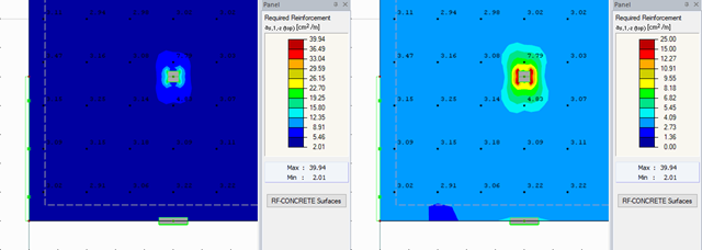
RFEM offers different options for the graphical display of results that have been determined in RF-CONCRETE Surfaces. This article gives an overview of these options.
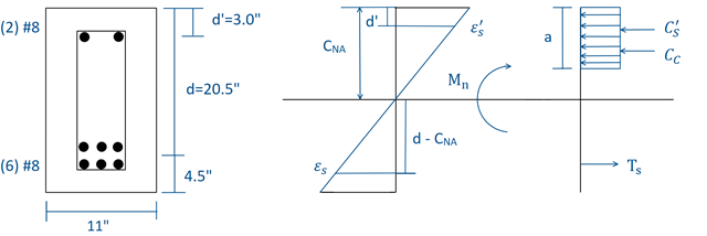
Using RF-CONCRETE Members, concrete beam design is possible according to ACI 318-14. Accurately designing concrete beam tension, compression, and shear reinforcement is important for safety considerations. The following article will confirm the reinforcement design in RF-CONCRETE Members using step-by-step analytical equations as per the ACI 318-14 standard, including moment strength, shear strength, and required reinforcement. The doubly reinforced concrete beam example analyzed includes shear reinforcement and will be designed under the ultimate limit state (ULS) design.
With RF-FOUNDATION Pro, it is possible to determine the settlements of single foundations and resulting spring stiffnesses of the nodal supports. These spring stiffnesses can be exported into the RFEM model and used for further analyses.

Different methods are available for calculating the deformation in the cracked state. RFEM provides an analytical method according to DIN EN 1992-1-1 7.4.3 and a physical-nonlinear analysis. Both methods have different features and can be more or less suitable depending on the circumstances. This article will give an overview of the two calculation methods.

In accordance with Sec. 6.6.3.1.1 and Sec. 10.14.1.2 of ACI 318-14 and CSA A23.3-14, respectively, RFEM effectively takes into consideration concrete member and surface stiffness reduction for various element types. Available selection types include cracked and uncracked walls, flat plates and slabs, beams, and columns. The multiplier factors available within the program are taken directly from Table 6.6.3.1.1(a) and Table 10.14.1.2.

Using RF-CONCRETE Members, concrete column design is possible according to ACI 318-14. Accurately designing concrete column shear and longitudinal reinforcement is important for safety considerations. The following article will confirm the reinforcement design in RF-CONCRETE Members using step-by-step analytical equations as per the ACI 318-14 standard, including required longitudinal steel reinforcement, gross cross-sectional area, and tie size/spacing.

Reinforced concrete surface design for slabs, plates, and walls is possible in the RF-CONCRETE Surfaces module according to the ACI 318-19 or the CSA A23.3-19 standard. A common approach for slab design is the use of design strips for determining the average one-way internal forces over the width of the strip. This design strip method essentially takes a two-way slab element and applies a simpler one-way approach to determine the required reinforcement needed along the strip length.

RF‑CONCRETE Surfaces for RFEM 5 allows you to use averaged internal forces for design of concrete surfaces.

In RFEM 5 and RSTAB 8, you can design foundations according to EN 1992‑1‑1 and EN 1997‑1 in the RF‑/FOUNDATION Pro add‑on module.

RF-CONCRETE Members for RFEM or CONCRETE for RSTAB propose an automatically created reinforcement to the user if the "Design the provided reinforcement" option is selected in Window 1.6 "Reinforcement".
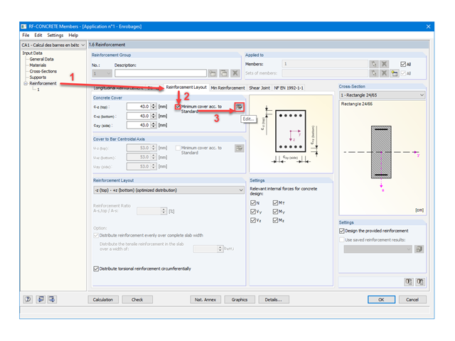
This article deals with the protection of reinforcement against corrosion defined according to EN 1992-1-1, also called concrete cover. The purpose of this article is to show how very many parameters defined in the Eurocodes for concrete reinforcements are considered in the RFEM structural analysis software.

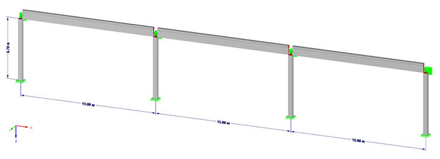
This article deals with the determination of the concrete reinforcement for a beam stressed by tension only according to EN 1992-1-1. The aim is to show the tensile load of a member-type element (without imposed deformations) and to define the concrete reinforcement in accordance with the standard's construction rules and provisions using the RFEM structural analysis software.
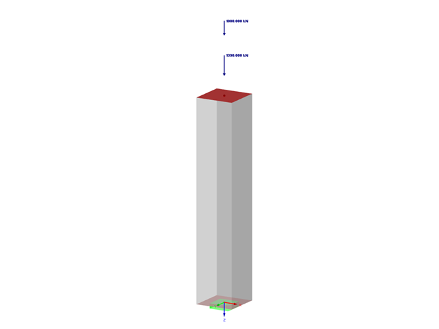
This article deals with rectilinear elements of which the cross-section is subjected to axial compressive force. The purpose of this article is to show how very many parameters defined in the Eurocodes for concrete column calculation are considered in the RFEM 5 structural analysis software.